Phone+98-912-028-0065

Investigation of the fouling layer growth using coupled immersed boundary and Eulerian-Lagrangian methods

Abstract

This paper simulates the growth of a fouling layer on the outer surface of pipes using the "Immersed Boundary" and "Eulerian-Lagrangian" methods. In this approach, the continuous fluid flow is modeled using the Eulerian framework, while suspended particles are tracked using the Lagrangian method. The Immersed Boundary method is employed to reduce computational costs compared to dynamic mesh techniques. The results show that particles smaller than 10 micrometers can penetrate behind the cylinder, while larger particles tend to accumulate at the front. An increase in Reynolds number reduces fouling mass due to enhanced surface shear stress and a decrease in critical deposition velocity.

1. Introduction

Fouling, the accumulation of particles on surfaces, is a major challenge in many industrial processes, particularly in heat exchangers and pipelines. It reduces heat transfer efficiency and can lead to increased pressure drops, system blockages, and higher operational costs. Understanding the mechanisms behind fouling layer growth is crucial for designing systems that mitigate its impact. Numerical simulations offer a powerful tool to study the complex, unsteady, and multiphase nature of fouling. This paper employs a coupled Eulerian-Lagrangian and Immersed Boundary method to simulate fouling on pipe surfaces, aiming to capture the detailed interactions between fluid flow, particle deposition, and fouling layer formation. The study focuses on key factors such as particle size, flow velocity, and Reynolds number, and provides insights into how these parameters influence fouling behavior.

2. Methodology & Solution

In this study, the growth of a fouling layer on the outer surface of a pipe within a two-dimensional channel is simulated using a combination of the Eulerian-Lagrangian method and the Immersed Boundary Method (IBM). The continuous phase (fluid) is modeled using the Eulerian approach, while suspended particles in the discrete phase are tracked using the Lagrangian method. The Immersed Boundary Method is employed to simulate the deformation and movement of solid boundaries without the need for mesh reconstruction, reducing computational costs by up to 30%.

Geometry Dimensions:
The geometry consists of a circular pipe with a diameter of 22 mm, located within a two-dimensional channel with a length of 300 mm and a width of 50 mm. This pipe is modeled as the surface where fouling occurs.

Boundary Conditions:
• Channel Inlet: Velocity inlet condition with a value of 1.93 m/s in the horizontal direction.
• Channel Outlet: Zero pressure boundary condition.
• Channel walls and pipe: No-slip condition for velocity and zero-gradient for pressure.

Solution Methodology:
OpenFOAM software is used to solve the problem, with a uniform mesh around the pipe. Particles are randomly injected from different points at the inlet, and their positions, forces, and velocities are updated at each time step. Particle collisions with the pipe surface are evaluated, and based on collision forces and adhesion, the deposition mass is calculated. A supporting algorithm is used to update the position of the fouling surface and manage fouling layer growth.

3. Flow Simulation and Validation Results

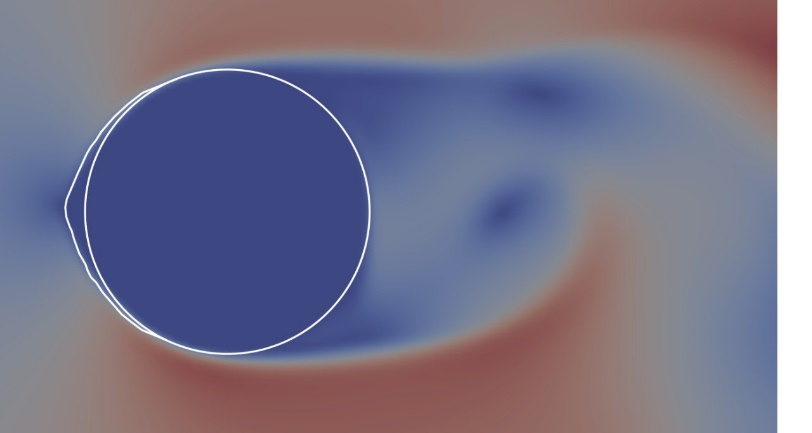
In this simulation, a combined Eulerian-Lagrangian model with the Immersed Boundary Method (IBM) was used to study the growth of the fouling layer on a pipe. This method helps reduce computational costs and allows for a detailed investigation of interactions between fluid flow and particle deposition. Particles are injected at each time step, and their forces, positions, and collisions with the pipe surface are evaluated. Collisions may lead to either adhesion or detachment of particles, depending on the adhesion and impact forces.

The Brownian motion of the particle is described by the Lagrangian equation: \[ \frac{du}{dt} + \beta u = n(t) \] The diffusion coefficient is calculated as: \[ D = \frac{KT}{\beta m} = \frac{KT C_c}{3\pi \mu d}

The simulation results showed that particles smaller than 10 micrometers penetrate behind the pipe, while larger particles (25-30 micrometers) predominantly accumulate in front of the pipe and deposit with nearly twice the frequency of smaller particles. Additionally, an increase in Reynolds number (Re) resulted in a 67% reduction in fouling mass due to increased surface shear stress and a decrease in critical deposition velocity.

Larger particles are more uniformly distributed across the surface of the pipe, particularly at different pipe angles, where they tend to accumulate more on the lateral sections. Furthermore, with increasing Young's modulus, for example, at a modulus of 50,000 MPa, fouling deposition is nearly eliminated. These findings are valuable for optimizing anti-fouling system designs and improving the efficiency of heat transfer equipment.

Figure 7 comparison of ash particle fouling layer growth on the boiler tube in the experimental work [1] and the present study (a) experimental work (b) present study.

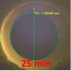
In Figure(1), the comparison of the growth of the deposit layer of ash particles on the boiler tube in the present and experimental work are compared. As shown in Fig(1), the results for fouling layer growth demonstrate acceptable accuracy.

Figure 8 Comparison of the change in the height of the ash fouling on the front of the boiler tube over time in Zheng's research and the present work [1].

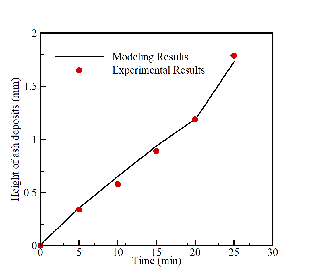
For further analysis, Fig 8 presents the graph of fouling height variation over time at the leading edge of the fouling layer, as reported by Zheng et al.[1]. The maximum error in this study is approximately 4%, which is attributed to the modeling of surface forces on the particles, where only key forces such as drag, lift, and gravity were considered.

4. References

[1] Z. Zheng et al., "Development of a mechanistic fouling model for predicting deposit formation in a woodchip-fired grate boiler," Energy, vol. 220, p. 119699, 2021.